E-ISSN:2583-9152

Research Article

Aberrated Coherent

Journal of Condensed Matter

2023 Volume 1 Number 2 Jul-Dec
Publisherwww.thecmrs.in

Variable Apodization Method to Reduce The Effect of Edge Ringing of Aberrated Coherent Optical Systems

Shailaja P1*, Rao S2, Sagar D3, Venkanna M4
DOI:10.61343/jcm.v1i02.28

1* P Shailaja, Department of Physics, Jawaharlal Nehru Technological University, Hyderabad, Telangana, India.

2 S Venkateshwara Rao, Department of Physics, Jawaharlal Nehru Technological University, Hyderabad, Telangana, India.

3 D Karuna Sagar, Department of Physics, BVRIT Hyderabad College of Engineering for Women, Hyderabad, Telangana, India.

4 M Venkanna, Optics Research Group, Department of Physics, Osmania University, Hyderabad, Telangana, India.

The coherent edge imaging of optical systems apodised with amplitude filters has been studied. Edge ringing can be appreciably mitigated using the chosen amplitude filters. The analytical studies were made for circular aperture. It is found that this type of apodization is more useful in reducing the ringing effect and also there is a perceptible increase in the edge gradient. Hence these amplitude filters are found to be effective in enhancing the resolving power aspects of edge imaging characteristics of optical systems.

Keywords: Apodization, coherence, aberrations, edge imaging, imaging systems

Corresponding Author How to Cite this Article To Browse
P Shailaja, , Department of Physics, Jawaharlal Nehru Technological University, Hyderabad, Telangana, India.
Email:
Shailaja P, Rao S, Sagar D, Venkanna M, Variable Apodization Method to Reduce The Effect of Edge Ringing of Aberrated Coherent Optical Systems. J.Con.Ma. 2023;1(2):105-112.
Available From
https://jcm.thecmrs.in/index.php/j/article/view/28

Manuscript Received Review Round 1 Review Round 2 Review Round 3 Accepted
2023-11-08 2023-11-13 2023-11-18 2023-11-24 2023-12-01
Conflict of Interest Funding Ethical Approval Plagiarism X-checker Note
None Nil Yes 19.78%

© 2023by Shailaja P, Rao S, Sagar D, Venkanna Mand Published by Condensed Matter Research Society. This is an Open Access article licensed under a Creative Commons Attribution 4.0 International License https://creativecommons.org/licenses/by/4.0/ unported [CC BY 4.0].

Introduction

In order to improve the results of an optical system, there are two methods namely modification of the optical system and post detection processing. The former involves choosing an optimum optical system itself and later involves operations on the system’s output. In many situations followed the first one by changing the pupil function with suitable apodisation. Apodisation is the technique that modifies the imaging properties of an optical system such that the system impulse does not show ringing by manipulating its entrance pupil. [1] The term "ringing" is most often used for ripples in the time domain, though it is also sometimes used for frequency domain effects. It is the visual obstruction and has to be minimized by some means. Edge gradient is the increase in the image intensity per unit change in Z around the geometrical edge, i.e., at Z = 0 [2]. In the present work an attempt has been made to surmount the problem of edge-ringing and improving edge-gradient in the image of straight opaque edges in coherent illumination by using variable apodisation method with the use of three different filters for various zones of transmission. Apodization is useful in improving selected aspects of the imaging performance of an aberrated optical system [3-6]. Several researchers have studied the edge-ringing and edge-shifting properties of different pupil functions with a motivation to improve the quality of images [7-9].

The existence of optical aberrations is a ubiquitous feature of all optical systems. Even the best-corrected systems have residual aberrations, and the majority of systems are not well-corrected. As the wave front travels through the optical systems, aberrations cause phase problems. Aberrations can lead to unfavorable outcomes and a decrease in optical system performance. In an aberrated optical system, edge ringing and edge shifting are more prominent than in an aberration-free one. Apodized images of coherently illuminated edges in the presence of aberrations were examined in depth by BARAKAT (1969) and ROWE (1969). Marechal has studied the best balancing conditions for a coherently lighted line in the presence of spherical aberration and defocusing (BORN and Marechal, 2007). Edge ringing, edge gradient, and edge shifting are three significant effects that impair the image in coherent imaging of

edge objects. The results of experiments on the impact of defocusing, coma, and primary spherical aberrations on the performance of apodized coherent optical imaging systems in the formation of straight edge images are reported in this work. Apodization can be achieved in a number of methods, including changing the aperture's geometry or transmission qualities [10]. The former is referred to as aperture shaping and it involves changing the shape and size of the aperture. Secondly an apodized filter over the pupil known as aperture shading. Thus, apodization is the deliberate manipulation of the pupil function to change the light distribution in the PSF in order to improve the quality of image [11].

Apodization is a subset of the more general spatial filtering approach (Hecht and Zajac, 1987). Apodization can help an aberrated optical system improve certain aspects of its imaging performance [12-14]. With the goal of improving image quality, some researchers have investigated the edge-ringing and edge-shifting aspects of various pupil functions [15-17]. The difference between the first maximum of the edge fringes and the unit object intensity is the edge ringing. Edge-shift, also known as image shift, is the distance between the image edge and half of the object edge's intensity value. The rise in image intensity over a unit change in Z around the geometric edge (i.e., Z=0) is known as an edge-gradient. Apodization can be utilized for a variety of objectives, including suppressing optical side-lobes in an optical imaging system's diffraction field [18-19], enhancing depth of field [20-24], and improving resolution [25-30]. The effectiveness of the apodization technique is constantly linked to the pupil function's design. It is well known that apodization, which is used to lower the size of the point spread function's focus spot, frequently results in the growth of side lobes. As a result, many techniques to reaching a compromise are examined [31-35].

Theory and Formulation

The mathematical expression of amplitude transmittance of an opaque straight edge object [36] is given by

 B(u, v) = 1 when u >= 0

 B(u, v) = 0 when u < 0                            (1)


It is evident that B (u) is a non-convergent and it does not permit Fourier transformation directly. However, this difficulty can be overcome by expressing it in terms of “signum” function as

Where  is expressed as

    B(U)=1/2[1+sgn(u)]

    sgn(u) = when u >= 0 

    = -1 when u<0                                          (2)

A sequence of transformable functions which approach  as a limit should be considered, as this function also has a discontinuity at u=0.

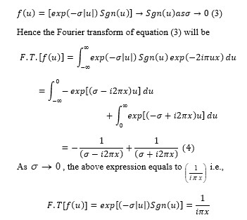
For example, the function
jcm_28_01.jpg
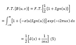
Thus, expressing the straight edge in terms of  as given in (2) and its Fourier transform can be obtained as
jcm_28_02.jpg
Here, ∂(x) is the well–known Dirac-delta function. The expression (5) represents the Fourier spectrum of the object amplitude distribution. In this spectrum, the presence of a large zero frequency impulse at  is observed, in addition to the other non-zero frequency components. Looking at the object function in fig (1), it appears at the first sight

that  is purely zero frequency input to the optical system and therefore, the presence of those non-zero frequencies in the spectrum of such an object may appear rather strange. It should be, however, observed that the object function has zero transmission over one-half in its own plane and a transmission equal to unity over the other half. In other words,  is zero for < 0 and then there is an abrupt discontinuity at . Thus,  is not a true D.C. signal as it is not constant over the entire interval ranging from  to  and this describes the presence of the other frequency components in the spectrum.

The imaging positions, encountered in optics are generally concerned with objects where amplitude or intensity variations are to be considered in two dimensions. The complex object amplitude distribution as defined in equation (1) implies that there is no variation in amplitude transmission of the object along the entire y-direction. This will give rise to an infinite impulse at  in the spectrum plane and can be represented by the Dirac-delta function . Finally, therefore, the two-dimensional F.T. of the object function is obtained as
  jcm_28_03.jpg
The above expression gives the amplitude distribution spectrum of the object  at the entrance pupil of the optical system. The modified amplitude distribution spectrum of object at the exit pupil of the optical system can be expressed as  
jcm_28_04.jpg
Here  represents the pupil function of the given optical system having aberrations and can be expressed as
jcm_28_05.jpg
Where f(x, y) denotes the amplitude transmittance over the pupil and (x, y) indicates the wave aberration function of the optical system. In the absence of apodization, f(x, y) is taken to be equal to unity i.e., for the Airy pupils, f(x, y) = 1.

For defocus, coma and primary spherical aberrations, the aberration function can be expressed as
jcm_28_06.jpg


Here -Defocus coefficient, -Primary spherical aberration coefficient and  - Coma and from the expressions (6), (7) and (8) the modified amplitude spectrum at the exit pupil is given by
jcm_28_07.jpg
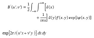
The above equation (9) gives the modified spectrum of the object at the exit pupil of the optical system. The amplitude distribution spectrum in the image plane will be given by the inverse Fourier Transform of expression (9). Therefore,jcm_28_08.jpg
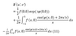
The integration limits of equation (10) are only formal because the pupil function given by T(x, y) vanishes outside the pupil and can be assumed to be unity inside. Thus, after some manipulation in the integration of Eq. (10) by employing the filtering property of Dirac-delta function the expression (10) can be simplified asjcm_28_09.jpg
The filtering property of Dirac-delta function is represented by  jcm_28_10.jpg
For the central transmittance of the pupil function f(0)=1, then the expression (11) can be expressed as
jcm_28_11.jpg
For the rotationally symmetric pupil function
jcm_28_12.jpg
Setting in equation (13), then it reduces to the more explicit formula for the image of an edge

object.
jcm_28_13.jpg
On further simplification equation (14) reduces to
jcm_28_14.jpg
Pupil function f(r) for the shaded aperture is given by
jcm_28_15.jpg
Here β is the apodization parameter controls the level of non-uniformity of transmission over the pupil. β= 0 corresponds to diffraction limited airy pupil with uniform transmission of unity.

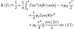
For the given pupil apodized with shaded aperture in the presence of defocus, primary spherical aberration and coma the expression (16) becomesjcm_28_16.jpg

The intensity distribution of an edge image formed by an apodized aberrated optical system is given by the squared modulus of expression (17)jcm_28_17.jpg

Results and Discussion

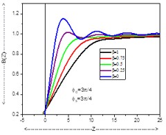
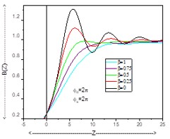
The investigations on the effects of defocus and primary spherical aberrations on the images of straight edge objects formed by coherent optical systems apodized by multiple amplitude filters in the case of circular aperture have been evaluated using the expression (5) by employing Matlab simulations. The intensity distribution in the images of straight edge objects has been obtained for different values of dimensionless diffraction variable 𝑍 varying from −5 to 25.
jcm_28_18.jpg style=


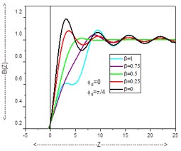
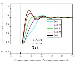
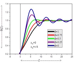
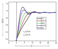
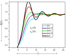
Figures 1, 2 and 3 gives intensity distribution curves in case of circular aperture of a variable apodizer for focused and defocused optical systems. It is observed that edge ringing is maximum for clear aperture (β=0). The edge ringing is reducing as apodization parameter β increasing from 0 to 1. Nevertheless, edge ringing is not fully reduced with single filter. In order to reduce further variable apodization is adopted.

jcm_28_19.jpg
Figure 1: Intensity distribution curves for single filtering

jcm_28_20.jpg
Figure 2: Intensity distribution curves for single filtering

jcm_28_21.jpg
Figure 3: Intensity distribution curves for single filtering

jcm_28_22.jpg
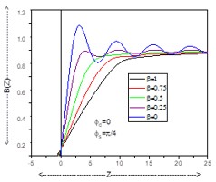
Figure 4:
Intensity distribution curves for double filtering

jcm_28_23.jpg
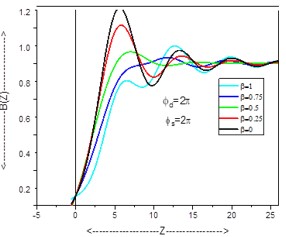
Figure 5: Intensity distribution curves for double filtering

jcm_28_24.jpg
Figure 6:
Intensity distribution curves for double filtering

Figures 4, 5 and 6 depicts that the edge ringing is maximum at  = 2π & β=0 and edge ringing is minimum at  =0 and β = 1.

(iii) f (r) = cos2 (πβr) * exp (-βr2) * (1-β r) - Triple Filtering


jcm_28_25.jpg
Figure 7:
Intensity distribution curves for Triple filtering

Figures 7, 8 and 9 demonstrate that the edge ringing is reduced at larger level in triple filtering compared to single and double filtering.

jcm_28_26.jpg
Figure 8:
Intensity distribution curves for Triple filtering

jcm_28_27.jpg
Figure 9: Intensity distribution curves for Triple filtering

Conclusions

As a result, this feature of reducing or eliminating edge ringing comes at the expense of increasing the edge shift and further losing edge gradient. The amplitude transmittance gradually decreases from the center of the pupil outward due to varying apodization. Due to apodization, the higher spatial frequency components of the image are reduced since the pupil transmittance at the margins is lower than that in the centre. As the apodization value goes from 0 to 1, the edge-ringing decreases along with the edge gradient at the expense of an increase in the edge shift. The single filter does not, however, totally eliminate edge ringing. The variable apodization has been implemented in an effort to further reduce or eliminate undesired ringing. As opposed to using a single filter, the double filtering technique reduces edge ringing to lower levels. Similar to this, undesired edge ringing is lessened or almost completely eliminated when the aberrated coherent optical system is shaded with three filters at once.

References

1. Barakat R, J. Opt.Soc.Am.52 264 (1964).

2. Araki T & Sakura T A, Opt Commun, 20, 373 (1977).

3. Barakat R. “Solution of the luneberg apodization problems”. J Opt Soc Am 1962; 52(3): 264-275. DOI: 10.1364/JOSA.52.000264.

4. Mills JP, Thompson BJ. “Effect of aberrations and apodization on the performance of coherent optical systems”. II. Imaging. J Opt Soc Am A 1986; 3(5): 704-716.

5. Venkanna M, Karuna Sagar D. “Reduction in edge-ringing in aberrated images of coherent edge objects by multishaded aperture”. Advances in Optics 2014; 2014: 963980. DOI: 10.1155/2014/963980.

6. Venkanna M, Karuna Sagar D. “Amplitude filters in shaping the point spread function of optical imaging systems”. Proc SPIE 2015; 9654: 96540A. DOI: 10.1117/12.2181610.

7. Katti PK, Gupta BN. “Effect of amplitude filter on the partially space coherent diffraction of a defocused optical system”. J Opt Soc Am 1972; 62(1): 41-44.


8. Tschunko HFA. Apodization and image contrast. Appl Opt 1979; 18(7): 955-956.

9. Araki T, Asakura T. Coherent apodization problems. Opt Commun 1997; 20(3): 373-377.

10. Hecht, E., Zajac, A., “Optics”, (Addison – Wesley, USA), 2nd Ed., p.422, 496, 497 & 512, (1987).

11. Wetherell, W.B. “Applied optics and optical engineering”, (Academic press, N.Y., Eds. R. R. Shannon & J.C. Wyant) vol.8, ch.6, p.173-283, (1980).

12. BARAKAT, R., “Solution of the Luneberg apodization problems”, J. OPT. SOC. AM., 52, P.264, 276 & 985, (1962). doi:10.1364/JOSA.52.000264

13. J. P. Mills and B. J. Thompson, “Effect of aberrations and apodization on the performance of coherent optical systems”, II. Imaging, Vol 3, pp 704, (1986).

14. Venkanna M. and Karuna Sagar D., “Reduction in edge-ringing in aberrated images of coherent edge objects by multishaded aperture”, J. of Advances in optics (2014). DOI:10.1155/2014/963980

15. P.K Katti and B.N. Gupta, “Effect of Amplitude filter on the partially Space Coherent diffraction of a Defocused optical System”, J. Opt. Soc. Am. 62, 1, 41-44
(1972)

16. Hubert F. A Tschunko, Apodization and Image Contrast, Appl.Opt. 18, 7, 955 (1979)

17. T.Araki and T. Asakura, Coherent Apodization Problems, Opt.Commu.20, 3,373-377 (1997)

18. Jacquinot P, Roizen-Dossier B. II Apodization. Prog.in Optics 1964; 3: 29-186. DOI:10.1016/S0079-6638(08)70570-5

19. Siu GG, Cheng L, Chiu DS. “Improved side-lobe suppression in asymmetric apodization”. J Phys D: Appl Phys 1994; 27(3): 459-463. DOI: 10.1088/0022-3727/27/3/005

20. Dowski ER, Cathey WT. “Extended depth of field through wavefront coding”. Appl Opt 1995; 34(11): 1859-1866. DOI: 10.1364/AO.34.001859.

21. Pan C, Chen J, Zhang R, Zhuang S. “The extension ratio of depth of field

by wavefront coding method”. Opt Ex-press 2008; 16(17): 13364-13371. DOI:
10.1364/OE.16.013364.

22. Khonina SN, Ustinov AV. “Generalized apodization of an incoherent imaging system aimed for extending the depth of focus”. Pattern Recognition and Image Analysis 2015; 25(4): 626-631. DOI: 10.1134/S1054661815040100

23. Dzyuba A.P., Serafimovich P.G., Khonina S.N., Popov S.B., “Application of a neural network for calculating the surface relief of a different level two-zone lens with an increased depth of field”, Proc. of SPIE Vol. 11516, 115161A (2020); DOI:10.1117/12.2565993.

24. Khonina S.N., Volotovskiy S.G., Dzyuba A.P., Serafimovich P.G., Popov S.B., and Butt M.A., “Power phase apodization study on compensation defocusing and chromatic aberration in the imaging system”, Electronics (MDPI) 10, 1327-(15p), (2021); DOI:10.3390/electronics10111327

25. Barakat R. “Application of apodization to increase Two-point resolution by Sparrow criterion under incoherent illumination”. JOSA 1962; 52(3): 276-283. DOI: 10.1364/JOSA.52.000276.

26. Kowalczyk M, Zapata-Rodriguez CJ, “Martinez-Corral M. Asymmetric apodization in confocal scanning systems”. Appl Opt 1998; 37(35): 8206-8214

27. Khonina S.N. and Ustinov A.V., “Sharper focal spot for a radially polarized beam using ring aperture with phase jump”, Journal of Engineering (Hindawi Publishing Corporation), ID 512971, 8 pp. (2013) DOI: 10.1155/2013/512971

28. Reddy A. N. K., Sagar D. K., Khonina S. N., “Complex pupil masks for aberrated imaging of closely spaced objects”, Optics and Spectroscopy, 123(6) 940–949 (2017), DOI: 10.1134/S0030400X17120189

29. Reddy, A.N.K., Khonina S.N., “Apodization for improving the two-point resolution of coherent optical systems with defect of focus”, Applied Physics B 124, 229-(9p) (2018); DOI: 10.1007/s00340-018-7101-z

30. Reddy A.N.K., Hashemi M., Khonina S.N., “Apodization of two-dimensional pupils with aberrations”, Pramana – Journal of Physics 90, 77-(8p) (2018); DOI: 10.1007/s12043-018-1566-5


31. Hopkins HH, Zalar B. “Aberration tolerances based on line spread function”, J Mod Opt 1987; 34(3): 371-406. DOI: 10.1080/09500348714550391.

32. Sheppard CJR, Choudhury A. “Annular pupils, radial polarization, and superresolution”, Appl Opt 2004; 43(22): 4322-4327. DOI: 10.1364/AO.43.004322

33. Ratnam C, Lakshman Rao V, Goud SL. “Comparison of PSF maxima and minima of multiple annuli coded aperture (MACA) and complementary multiple annuli coded
aperture (CMACA) systems”, J Phys D: Appl Phys 2006; 39: 4148-4152. DOI: 10.1088/0022-3727/39/19/005.

34. Khonina SN, Ustinov AV, Pelevina EA. “Analysis of wave aberration influence on reducing the focal spot size in a high-aperture focusing system”, J Opt 2011; 13(9): DOI: 10.1088/2040-8978/13/9/095702

35. Khonina S.N., Volotovskiy S.G., “Minimizing the bright/shadow focal spot size with controlled side-lobe in-crease in high-numerical-aperture focusing systems”, Advances in Optical Technologies (Hindawi Publishing Cor-poration), Volume 2013, Article ID 267684, 13pages, DOI: 10.1155/2013/267684.

36. T. Araki And T Asakura, “Apodized Images Of Coherently Illuminated Edges In The Presence Of Defocusing And Spherical Aberration”, Optika Aplicata, 1978 Viii/4, 159-170.